Tektronix DPO2EMBD
Embedded Serial Triggering and Analysis Module for MSO/DPO2000B Series (I2C, SPI)
Tektronix DPO2EMBD
Embedded Serial Triggering and Analysis Module for MSO/DPO2000B Series (I2C, SPI)
- Brand Name: Tektronix
- Condition: NEW
- Country of Origin: China
- Automated serial triggering, decoding, and search options for I2C and SPI
- Trigger on all critical elements of serial buses
- Decode all critical elements of each message (no more counting 1s and 0s)
- Search through long acquisitions using user-defined criteria to find specific messages
- Search mark table provides tabular view of events found during automated searches
- Export search mark table data to .csv files
- Event table shows decoded serial bus activity in tabular, timestamped format for quick summary of system activity
- Export event table data to .csv files
- For use with MSO/DPO2000 Series
The Tektronix DPO2EMBD Embedded Serial Triggering and Analysis Module for MSO/DPO2000B Series (I2C, SPI) enables triggering on packet-level information on I2C and SPI buses as well as analytical tools such as digital views of the signal, bus views, packet decoding, search tools, and packet decode tables with time-stamp information.
Application modules have licenses which can be transferred between an application module and an oscilloscope. The Tektronix DPO2EMBD's license maybe contained in the module; it can be moved from one instrument to another. Or, the license can be contained in the oscilloscope, allowing the module to be removed and stored for safekeeping. The license can also be transferred back to the module for use in another MSO/DPO2000B oscilloscope. Transferring the license to an oscilloscope and removing the Tektronix DPO2EMBD module permits the simultaneous use of more than two applications.
Serial Triggering and Analysis Application Modules
On a serial bus, a single signal often includes address, control, data, and clock information. This can make isolating events of interest difficult. The Serial Application modules for the MSO/DPO2000B Series transform the oscilloscope into a robust tool for debugging serial buses with automatic trigger, decode, and search for I2C and SPI.
Serial Triggering
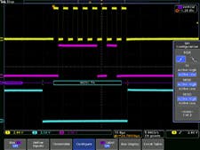
Trigger on packet content such as start of packet, specific addresses, specific data content, unique identifiers, etc. on I2C and SPI serial interfaces.
Bus Display
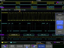
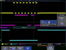
Provides a higher-level, combined view of the individual signals (clock, data, chip enable, etc.) that make up your bus, making it easy to identify where packets begin and end and identifying sub-packet components such as address, data, identifier, CRC, etc.
Bus Decoding
Once you have set up a bus, the oscilloscope will decode each packet on the bus, and display the value in signed decimal.
Search
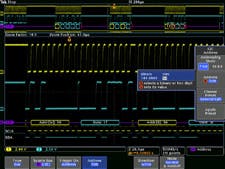
Serial triggering is very useful for isolating the event of interest. In the past, users had to manually scroll through the waveform counting and converting bits and looking for what caused the event. With a Serial Application module, you can enable the oscilloscope to automatically search through the acquired data for user-defined criteria including serial packet content. Each occurrence is highlighted by a search mark. Rapid navigation between marks is as simple as pressing the Previous and Next buttons on the oscilloscope front panel. The Search Mark table provides a tabular view of all events found during an automated search. The search mark data can be exported to a .csv file.
Event Table
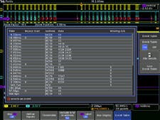
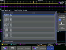
In addition to seeing decoded packet data on the bus waveform itself, you can view all captured packets in a tabular view much like you would see in a software listing. Packets are time stamped and listed consecutively with columns for each component (Address, Data, etc.).
I2C Characteristics:
- Bus setup options:
- Sources (clock and data):
- Analog channels 1-4
- Digital channels D0-D15
- Thresholds: Per-channel thresholds
- Recommended probing: Single ended
- Include R/W in address: Yes or no
- Decode formats available: Hex, binary
- Display modes:
- Bus: Bus only
- Bus and waveforms: Simultaneous display of bus and logic waveforms
- Event table: Decoded packet data in a tabular view
- Sources (clock and data):
- Bus trigger and search options:
- Trigger and/or search on:
- Start
- Stop
- Repeated start
- Missing ack
- Address (7 or 10 bit) with R/W selection
- Data (number of bytes 1-5)
- Address and data
- Trigger and/or search on:
- Bus decode:
- Maximum clock/data rate: Up to 10 Mb/s (for automated decoding of bus)
- Decode display:
- Start (green bracket)
- Address (yellow box)
- Missing ack (red ! symbol)
- Data (cyan box)
- Stop (red bracket)
SPI Characteristics:
- Bus setup options:
- Sources (clock, slave select, MOSI, and MISO):
- Analog channels 1-4
- Digital channels D0-D15
- Thresholds: Per-channel thresholds
- Recommended probing: Single ended
- Decode configuration:
- Framing:
- Idle time (2-wire SPI)
- Slave select (3-wire or 4-wire SPI)
- Clock: Rising or falling edge
- Slave select: Active high or active low
- MOSI: Active high or active low
- MISO: Active high or active low
- Word size: 4-32 bits
- Bit order:
- Most Significant (MS) first
- Least Significant (LS) first
- Framing:
- Decode formats available: Hex, binary
- Display modes:
- Bus: Bus only
- Bus and waveforms: Simultaneous display of bus and logic waveforms
- Event table: Decoded packet data in a tabular view
- Sources (clock, slave select, MOSI, and MISO):
- Bus trigger and search options:
- Trigger and/or search on:
- SS active
- Start of frame
- MOSI
- MISO
- MOSI and MISO
- Data: maximum of 128 bits (up to four 32-bit words or 32 four-bit words)
- Trigger and/or search on:
- Bus decode:
- Maximum clock/data rate: Up to 50 Mb/s (for automated decoding of bus)
- Decode display:
- Start (green bracket)
- Data (cyan box)
- Stop (red bracket)
| Country of Origin | China |
|---|---|
| Brand | Tektronix |
| Condition | NEW |
| Vendor Alias | TEK-DPO2EMBD |


